
A list of fuses and associated equipment
Fuse location and rating
| Fuse Number | Rating (AMPS) |
|---|---|
| 1 | 15 |
| 2 | 7.5 |
| 3 | 7.5 |
| 4 | 7.5 |
| 5 | 10 |
| 6 | 15 |
| 7 | 15 |
| 8 | 7.5 |
| 9 | 15 |
| 10 | 7.5 |
| 11 | 7.5 |
| 12 | 15 |
| 13 | 7.5 |
| 14 | 7.5 |
| 15 | 7.5 |
| 16 | 30 |
| 17 | 7.5 |
| 18 | 15 |
| 19 | 30 |
| 20 | 10 |
| 21 | 10 |
| 22 | 20 |
| 23 | 15 |
| 24 | 10 |
| 25 | 30 |
| 26 | 30 |
| 27 | 7.5 |
| 28 | 15 |
Equipment
| Equipment | Fuse |
|---|---|
| Air Conditioning | 9, 20, 27, 29 |
| Auxiliary Fan | 25, 29 |
| Auxiliary Water Pump | 9, 29 |
| Charge Socket | 21 |
| Check Control Module | 1, 20 |
| Cigarette Lighter | 26 |
| Clock | 20 |
| Control Lighting, License Plate, and Engine Compartment Lights | 25 |
| Cruise Control | 1 |
| Front Seat Heating | 16 |
| Fuel Pump | 23 |
| Gear-shift Level Lighting (Automatic Transmission) | 17 |
| Glove-box Lighting and Rear Reading Lamps | 18 |
| Headlight Cleaning System | 22 |
| Heated Rear Window | 28 |
| Heated Water Jets | 12 |
| Heater Blower | 19 |
| Heater Control | 20, 27 |
| Horn | 9 |
| Independent Heater and Ventilation | 1, 20, 28 |
| Instrument Cluster | 1, 17, 20 |
| Interior and Luggage Compartment Lighting | 21 |
| Brake Lights | 1, 15 |
| Fog Lights | 3, 7 |
| Hazard Warning Flasher | 6 |
| Headlight Flasher | 3 |
| High-beam Headlight, Left | 2, 13 |
| High-beam Headlight, Right | 2, 14 |
| Low-beam Headlight, Left | 2, 10 |
| Low-beam Headlight, Right | 2, 11 |
| Parking Light, Left | 4 |
| Parking Light, Right | 5 |
| Rear Fog Lights | 3,8 |
| Reversing Lights | 12 |
| Turn Indicators | 3, 6 |
| Lumbar Support | 16 |
| Mirror Adjustment | 12 |
| On-board Computer | 1, 17, 20 |
| Parking Aid | 12 |
| Radio | 18 |
| Rear Head Restraints | 17 |
| Rear Seat Heating | 17 |
| Rear Wiper | 18 |
| Roller Sun Blind | 18 |
| Servotronic Power Steering | 28 |
| Telephone | 18, 28 |
| Trailer | 18 |
| Windshield Wipers | 4, 2 |
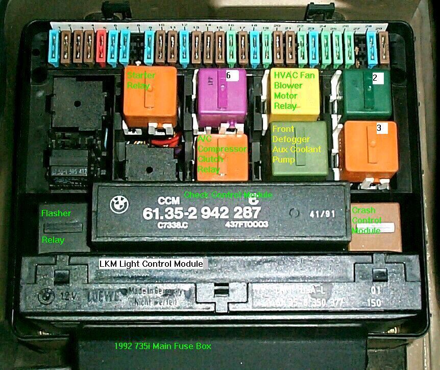
Relay box diagram
How to perform a stomp test for the check engine light
Procedure
- Turn ignition key to position 2 (just before cranking the engine)
- Fully depress the accelerator to the floor 5 times within 5 seconds
- The check engine light (CEL) will stay on for 5 seconds, blink off, come on for 2.5 seconds, then go off for 2.5 seconds. At this point, the fault codes will begin to flash
- Each flash is a +1 and a pause indicates indicates that the system is moving on to the next number
- There could be multiple codes. I just write down all the calculated numbers in a single row and break them down into four characters after
Fault codes
| Code | Description |
|---|---|
| 1211 | DME Control Unit |
| 1215 | Air Mass Sensor |
| 1216 | Throttle Position Sensor |
| 1218 | Output Stage, Group 1 |
| 1219 | Output Stage, Group 2 |
| 1221 | Oxygen Sensor 1 |
| 1212 | Oxygen Sensor 2 |
| 1222 | Lambda Control 1 |
| 1213 | Lambda Control 2 |
| 1223 | Coolant Temperature Sensor |
| 1224 | Intake Air Temperature Sensor |
| 1225 | Knock Sensor 1 |
| 1226 | Knock Sensor 2 |
| 1227 | Knock Sensor 3 |
| 1228 | Knock Sensor 4 |
| 1231 | Battery Voltage/DME Main Relay |
| 1232 | Throttle Idle Switch |
| 1233 | Throttle Wide Open Throttle Switch |
| 1234 | Speedometer A Signal |
| 1237 | A/C Compressor Cut Off |
| 1242 | A/C Compressor |
| 1243 | Crankshaft Pulse Sensor |
| 1244 | Camshaft Sensor |
| 1245 | Intervention AEGS |
| 1247 | Ignition Secondary Monitor |
| 1251 | Fuel Injector 1 (or group 1 for DME 1.3, cylinders 1, 3, 5) |
| 1252 | Fuel Injector 2 (or group 2 for DME 1.3, cylinders 2, 4, 6) |
| 1251 | Fuel Injector 1 |
| 1252 | Fuel Injector 2 |
| 1253 | Fuel Injector 3 |
| 1254 | Fuel Injector 4 |
| 1255 | Fuel Injector 5 |
| 1256 | Fuel Injector 6 |
| 1257 | Fuel Injector 7 |
| 1258 | Fuel Injector 8 |
| 1261 | Fuel Pump Relay Control |
| 1262 | Idle Speed Actuator |
| 1263 | Purge Valve |
| 1264 | EGO Heater |
| 1265 | Fault Lamp (check engine light) |
| 1266 | VANOS |
| 1267 | Air Pump Relay Control |
| 1271 | Ignition Coil 1 |
| 1272 | Ignition Coil 2 |
| 1273 | Ignition Coil 3 |
| 1274 | Ignition Coil 4 |
| 1275 | Ignition Coil 5 |
| 1276 | Ignition Coil 6 |
| 1277 | Ignition Coil 7 |
| 1278 | Ignition Coil 8 |
| 1281 | Control Unit Memory Supply |
| 1282 | Fault Code Memory |
| 1283 | Fuel Injector Output Stage |
| 1286 | Knock Control Test Pulse |
| 1444 | No Fault Codes stored |
| 1000 | End of fault code output |
Erasing fault codes
First make sure the fault code 1000 (short blink and then the light goes out for a long period) is present, then depress the throttle fully for at least 10 seconds. To confirm, repeat the stomp test to look for code 1444 (no faults stored).
Troubleshooting the onboard computer (OBC)
Broken bulb or no power?
If your car has an OBC with 1000,100,10,1 button, there is an easy way to test if the OBC is not getting power or if the bulbs are burned out.
- Turn the key position 2
- Press TIMER
- Press SET-RES
The TIMER button has a little red light that should light up now. If the light lit up, your OBC is getting power.
Finding an active short circuit
Disconnect the negative cable from the battery and put a test light across the negative cable and negative battery post. An active short will trigger the test light. Start pulling the fuses, one by one, until the light goes out – that fuse is powering a short circuit.
Specifications for electrical components
Internal engine sensors
- The camshaft sensor: 1280 +/- 10% Ohm
- The crankshaft sensor, terminal #1 and #2: 500 Ohm
Coolant and air temperature sensors
- 14F: 7-11 Ohm
- 78F: 2.1-2.9 Ohm
Throttle position sensor (TPS)
- With the ignition on:
- Measuring across terminal #1 and the ground: 5 VDC
- With the ignition off:
- Measuring across terminal #1 and #3: 4K Ohm
- Full throttle:
- Measuring across terminal #1 and #2: 1-4K Ohm
Idle valve control (ICV)
- Measuring across terminal #1 and #2: 12 +/- 2 Ohm
- Measuring across terminal #2 and #3: 12 +/- 2 Ohm
- Measuring across terminal #1 and #3: 23 +/- 4 Ohm
Battery
- With the ignition off:
- Measuring across negative and positive terminal: 12.24v or higher
- Battery charge breakdown:
- 12.66v . . . . . . . . . . 100%
- 12.45v . . . . . . . . . . 75%
- 12.24v . . . . . . . . . . 50%
- 12.06v . . . . . . . . . . 25%
- 11.89v . . . . . . . . . . 0%
Fixing continuously erratic or rough idle
Check the maintenance records for spark plugs. Did it recently get cold, and you are running high weight oil? If the car begins to idle better after 10-30 seconds it might be the oil. It can also be one of the following:
- Inspect and replace the intake air filter
- Check the resistance and clean the idle control valve
- Inspect the intake system for air leaks
- If you feel like it's a misfire condition, pull the electrical connector for each ignition and verify the engine idle drops. Inspect the coil, boot, fuel injector, and the spark plug on the cylinder if it drops
- Test the fuel pressure. Could be prioritized if the car cuts off when you give it gas
Troubleshooting a weak, stumbling start condition
- Check the battery with a handheld battery tester or get a free battery diagnosis at your local Autozone store
- You can turn the high beams on and start the car. If the lights dim then your battery does not have enough juice
- Clean the battery terminals and make sure the connectors are tight and rust-free
- Check the negative battery cable and make sure the other end is making proper, clean contact with the car frame
- Check maintenance history for the starter, and if the history is missing then it's probably a good idea to replace it
- Note that leaking rear main oil seal will coat your starter in oil, which will result in all sorts of weird starting conditions. Let the car sit for a couple of days and check the pavement for oil leaks
- Check the resistance of camshaft and crankshaft sensor
Aftermarket Viper alarm and central locking system
Central locking system
Fixing the double lock issue
A mismatched GM will cause miscommunication between the module and the central locking system. The miscommunication will cause GM to unlock the doors after you attempt to lock them with a remote, and the fix requires replacement of the GM with a unit that matches your car.
See the service bulletin below for part numbers:
Repeating the first command then results in carrying out that command (e.g., try to lock again, and locking is now carried out). This function ("Asynchronous Position") is omitted in the new GM for all E32 models and E34 models prior to 9/91(P/N 61358356095), and remains in the new GM for E34 models after 9/91 (P/N 61358355812) only for central locking commands "lock" and "double-lock".
If the doors were unlocked due to crash sensor activation, the locking command must be reactivated by double-locking with the master key from either the driver or passenger door.
System synchronization
After manually locking or unlocking the system, the door locks may become unsynchronized. Follow the following steps to complete the synchronization process:
- Close all doors, trunk lid, and tailgate
- Lock the passenger door by turning the key clockwise into the emergency locking position. Approximately 110 degrees from position O
- Unlock the driver's side door.
- If any of the locks do not operate, repeat the locking procedure until the locking system is synchronized.
Viper alarm
How to exit the valet mode
- Open the driver side door
- Turn the ignition to the second position (do not start the car) and off
- Press and hold the valet button for 5 seconds. Release when you hear an audible chirp
- Quickly press and release the valet button 2 times
- Press the valet button for the third time and hold it until you hear two audible beeps
- Keep holding the valet button after you hear the beeps and turn the ignition back to the second position
How to synchronize a new transmitter
- Get in the car and close all of the doors
- Cycle the ignition from first the second position quickly to start the synchronization routine. Do not take more than five seconds – the next step must be performed under 30 seconds
- Remove the key from the ignition and hold it near the transmitter. The transmitter antenna is usually mounted near the rear or front windshield
- Hold down the unlock button and press the lock button 3 times. Release the unlock button. The doors will lock to confirm successful synchronization
- Repeat the steps to synchronize additional keys
Installation guide for Viper 350HV
How to test a Bosch alternator
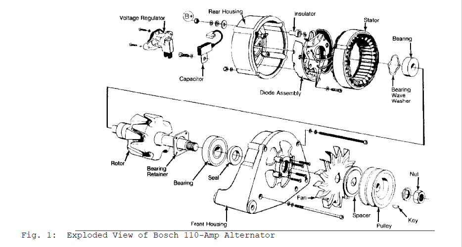
Bosch alternators are conventional 3-phase, self-rectifying type alternators. Bosch 110-amp alternators use 14 diodes. All alternators use 3 exciter diodes connected to stator windings. These diodes turn off the alternator indicator light and supply power to the voltage regulator while the engine is running. Bosch regulators are transistorized and integral with the alternator.
Wiring continuity test
- Connect a voltmeter between alternator Red battery terminal wire and ground. The voltmeter should indicate battery voltage. If not, check the wiring between alternator and battery.
- Turn the ignition on. Ensure alternator indicator light comes on. If the light does not come on, check wiring between alternator and warning light, including indicator bulb.
Alternator exciter circuit test
Current test
Check that battery voltage is a minimum of 12 volts. Charge as needed. Disconnect the Blue wire from the alternator terminal and connect a multimeter between alternator terminal and Blue wire. Set multimeter to 200-mA range. If reading is lower than 150-185 mA, check Blue wire between alternator and instrument panel or replace printed circuit in the instrument cluster.
Checking resistance
Disconnect the negative battery cable. Disconnect the blue wire terminal of the alternator. Connect Multimeter (US 1119) between blue wire and battery positive. Turn the ignition.
Checking output
- Ensure connections at battery, alternator, and starter are clean and tight. Ensure alternator, engine, and body are properly grounded. Ensure the alternator drive belt is tight and in good condition.
- Connect Ammeter/Voltmeter (VAT-40/60) or equivalent, following manufacturer's instructions. Connect voltmeter leads to battery terminals. Connect Green clamp (ammeter inductive pick-up) to alternator Brown/Yellow wire to the battery (positive post). Start the engine and allow to idle. Alternator output should be 20-30 amps.
- Repeat test at 2000 RPM. Alternator output should be 90- 110 amps or within 10 percent of the manufacturer's specification. If alternator output is low, remove alternator for testing and repairs. If reading is 16-20 amps less than alternator rating, replace regulator and re-test. Repair or replace the alternator if the condition persists.
Diode assembly bench testing
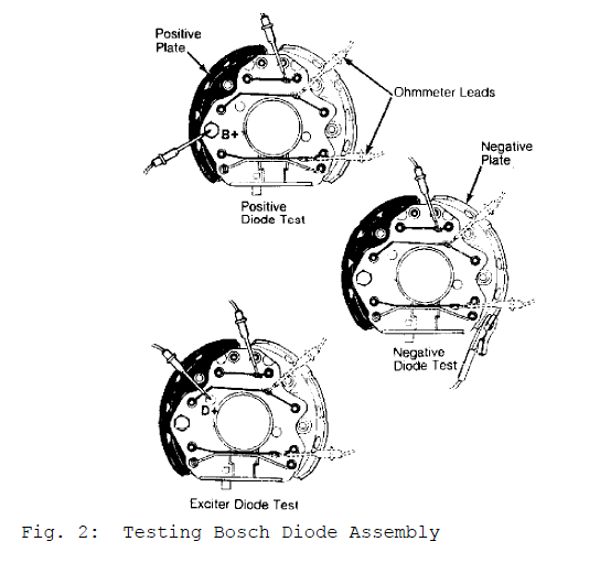
- Place ohmmeter on x100 scale. Connect ohmmeter leads across B+ terminal and each of the 3 stator terminals, in turn. Reverse leads. The ohmmeter should indicate continuity in one direction only.
- Connect ohmmeter leads across the negative plate and each of the 3 stator terminals, in turn. See Fig. 2. Reverse leads. The ohmmeter should indicate continuity in one direction only.
- Connect ohmmeter leads across D+ terminal and each of the 3 stator terminals, in turn. Reverse leads. The ohmmeter should indicate continuity in one direction only. Replace diode assembly if defective.
Stator bench testing
- Place ohmmeter on the lowest scale. Connect an ohmmeter across stator leads. The resistance between leads should be approximately .09-.10 ohm. If resistance is incorrect, the stator has open or shorted windings and must be replaced.
- Place ohmmeter on x1000 scale. Connect ohmmeter between the stator core and stator lead. No continuity should exist. If continuity exists, the stator is grounded and must be replaced.
Rotor bench testing
- Place ohmmeter on the lowest scale. Connect an ohmmeter across slip rings. Resistance should be 2.8-3.1 ohms.
- If resistance is too low, the rotor has a short circuit and must be replaced. If resistance is infinity (no continuity), the rotor has an open circuit and must be replaced.
- Place ohmmeter on x1000 scale. Connect ohmmeter between either slip ring and rotor core. No continuity should exist. If continuity exists, the rotor is grounded and must be replaced.
- Clean slip rings using fine sandpaper. Rings that are worn or pitted should be turned on the lathe. The minimum ring diameter is 1 1/16" (27 mm).
- If slip rings are beyond repair, remove the rear bearing from the slip ring end of the rotor. Unsolder wires from slip ring and bend up ends of the rotor winding. Pull off slip rings. Ensure ends of rotor winding are not damaged.
- Insert ends of rotor winding into the slip ring and press a new slip ring onto the rotor. Slip ring end must be 9/64" (3.57 mm) from the end of the collar. Solder rotor winding to slip ring terminals. Turn rings on lathe and retest rotor. Maximum slip ring run-out is .0012" (.03 mm).
Bearings bench testing
Always replace bearings when overhauling alternator. If replacement front bearing is sealed on one side only, the open side must face rotor. If replacement rear bearing is sealed on one side only, the open side must face away from the rotor.
Brushes bench testing
Ensure brushes are longer than 7/32" (5.56 mm). Replace if necessary. Unsolder brushes from the voltage regulator. Solder new brushes. Do not allow the solder to run into strands of brush leads. Brushes must be free to slide in brush holders with normal spring tension of 10-14 ozs. (283-397 g).
Converting the headlights to Xenon HID
The light technology has progressed significantly since our cars were manufactured, and when compared to modern applications, general road visibility in dark or rain conditions is a considered weak point.
If visibility is a hot topic for you, there are a lot of high-quality aftermarket conversion kits. The kits are durable, and the installation is pretty straightforward.
The setup I ended-up with provides optimal visibility in fog and rain conditions without making me look like a douchebag. You don't want your classic car to look like something that came off the set of The Fast and the Furious.
- For low beams, I went with 55W 4500K H1 bulbs
- For fog lights, I went with 35W 3500K H1 bulbs
- Note that slim ballast is preferred for both applications
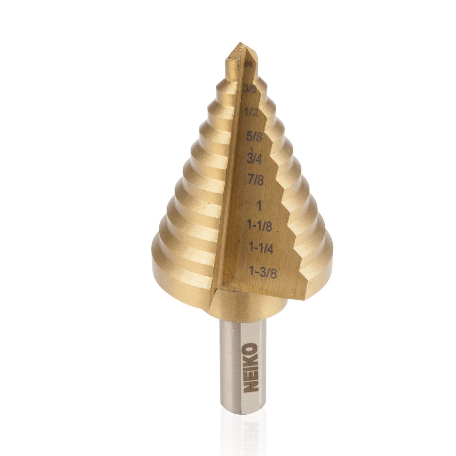
Please use a step drill for rear plastic bulb housing. You want the setup to be as insulated as possible.
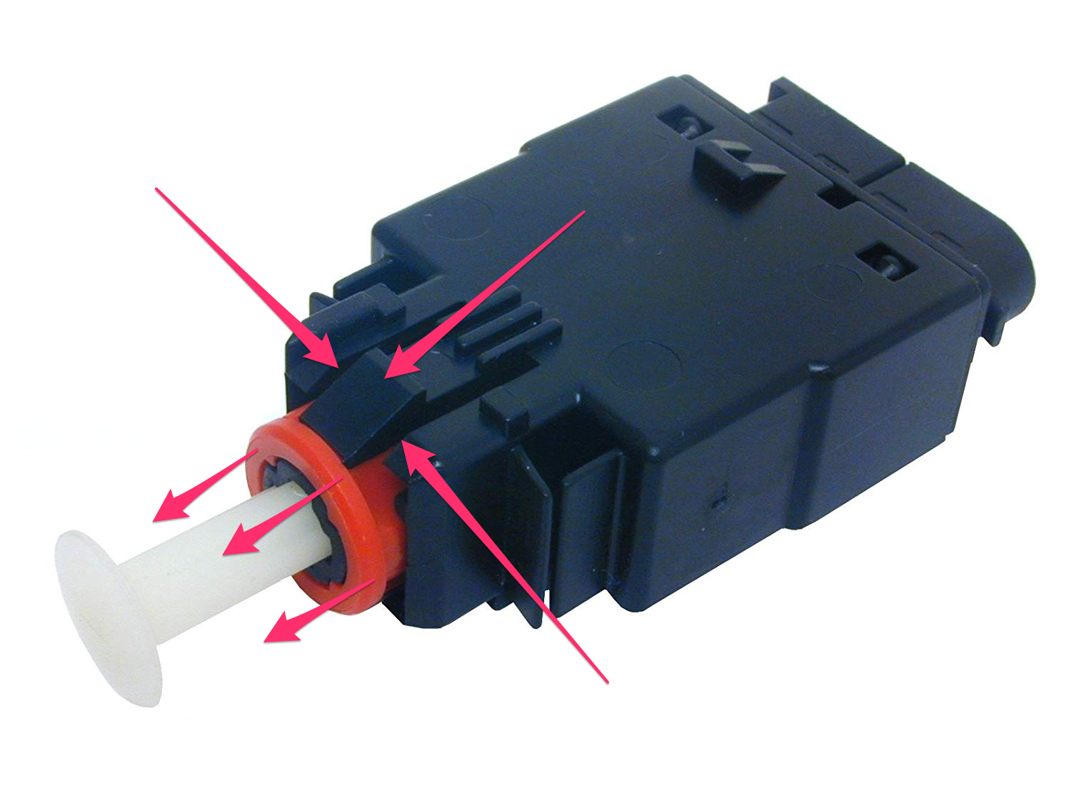
How to troubleshoot sticky brake lights
You may have a faulty or a loosely mounted brake light switch sensor if your brake lights are always on or do not light up when you engage the brake pedal.
The brake light switch is located just above the brake pedal and is plugged in face down. The spring switch sits between the mount and brake pedal and activates the brake lights when the pedal is pressed.
Inspect the connections running to the switch and verify that the switch bounces back after the full press.
To replace, grab a flat head screwdriver and push the red plastic cover all the way up – as shown in the picture. The red cover will prevent you from pressing in the clips that secure the switch to the floor mount.
Exercise caution when replacing alternator or power steering lines
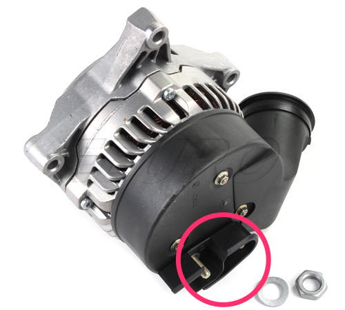
Be very careful if you are planning on touching your alternator or power steering lines. The positive thread on some of the alternators is excessively long and touches the primary power steering line once the alternator is mounted. I came across two alternators like this and can't recall if it's a rebuild issue or if Bosch revised their manufacturing process.
Use a Dremel if the positive thread sticks out the black plastic housing and make sure to unplug your battery to test fit the alternator or power steering line replacement.
These alternators do not come with a standard protective rubber cap on the positive terminal, so I had to create my own with a couple of layers of liquid tape.
It's always a good idea to verify the visual gap with a quick short circuit check. Check the positive alternator cable for Ohm/continuity against a known ground before the battery is connected.
Colors and features of a 25-pin V8 engine plug
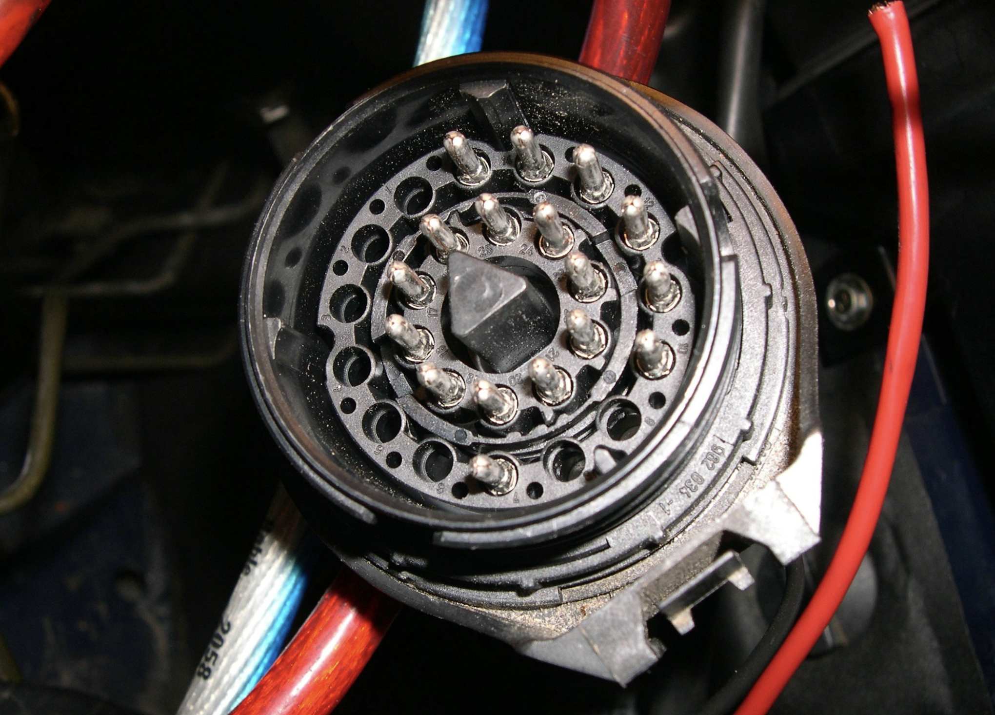
The provided chart also includes potential mapping points for wiring an E34 V8 (M60) engine with E30 harness.
| Pin | Wire | Function | Notes | Pin E30 |
|---|---|---|---|---|
| 1 | white | Oil-level static | 0.75 | 2 |
| 2 | blue white | Oil-level dynamic | 0.75 | 10 |
| 3 | red blue | ABS supply | 1.5, only required for E30 from '89 with ABS | 20 |
| 4 | black green | omit | ||
| 5 | black and white | omit | ||
| 6 | black blue | omit | ||
| 7 | black yellow | omit | ||
| 8 | white | omit | ||
| 9 | empty | omit | ||
| 10 | empty | omit | ||
| 11 | brown yellow | thermometer | 0.75 | 4 |
| 12 | yellow white | thermometer mass | omit | |
| 13 | grunlila | fuel pump | 1 | 13 |
| 14 | black white | speed signal | white plug to tachometer | b12 on speedometer |
| 15 | green black | relief relay | 1.5 | 15 |
| 16 | braunlila | diagnose vehicle wake | omit | |
| 17 | weisslila | vehicle diagnostic data link | omit | |
| 18 | black yellow | starter terminal | 1.5 | 18 |
| 19 | white green | display | 0.5 | 11 |
| 20 | black | rev counter | 0.75 | 9 |
| 21 | green | ignition | 2.5 | 7 |
| 22 | green white | supply diagnostic connector with | 6 | |
| 23 | brown green | oil pressure | 0.75 | 5 |
| 24 | white black | consumption display | 8 | |
| 25 | blue | alternator | 0.75 | 1 |